Activities and deliverables at system level
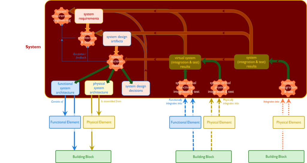
The image above shows the activities (gears) and the deliverables (rectangles) at system level.
Starting at the top left the system requirements engineering process delivers the system requirements as input for the system architecture & design process. The design artifacts (including the proposed functional & physical architectures) are input for the system decision-making process. Once the decisions have been taken and documented as design decisions, the design artifacts can be released and used as references for the System Elements on the next abstraction level.
Important characteristics of the W-model at system level:
- the functional and physical architecture are part of the system’s design artefacts and serve as starting points for system’s decomposition. They form the two left legs of the W-model;
- the virtual functional and physical integration and test processes demonstrate that the system requirements are met by the system’s design. They form the end points of the two middle legs (information flow is going upwards).
- after implementation of the Building Blocks, the system’s integration & test processes demonstrate that the system build meets is requirements. This is the right leg of the W-model (information flow upwards).
- feedback (and escalation) cycles are in place
- at system level the three specification types are documented:
- the system as required by the system requirements
- the system as designed by the system design decisions
- the system as build by the system test results
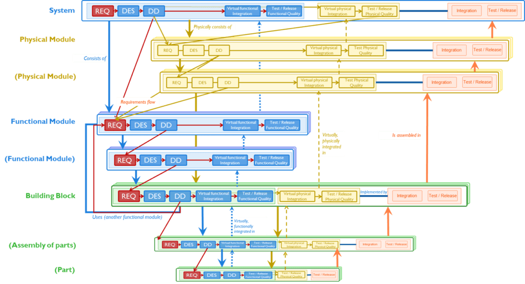
IMPULS3 W-model
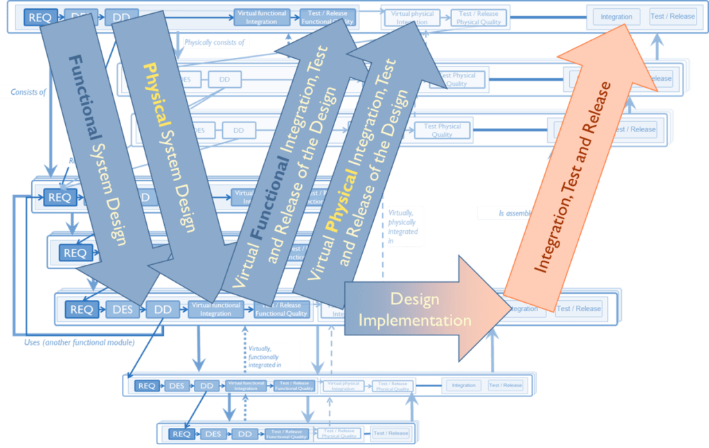
The W-model typically shows a flow of information from the top left down to the implementation processes and back up trough firstly the integration and test processes and then through the assembly/production processes.
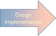
The two blue arrows from top left to implementation, depict two parallel design paths are created; one for the functional breakdown and one for the physical breakdown. The depth of each of these breakdowns (in terms of decomposition levels) depends highly on the size and complexity of the System of Interest.
The implementation arrow depicts the process of implementing the detailed design into hardware or software. This implementation takes place in two stages: (1) the blue part – a virtual implementation and (2) the orange part – a physical implementation.
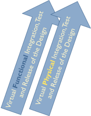
The blue integration arrow depicts the integration of the virtually implemented components. This virtual integration is based on the components present in PLM systems as model parts / drawings or software configuration management systems. This could be seen as an integration on paper.
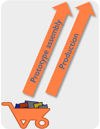
Based on the physically implemented components, the physical integration and testing can be done. Typically one or more prototypes are build, and after successful validation, the System of Interest can be produced. This sequence depends on the nature of the SoI. In case the SoI is a bridge, it seems very unlikely that more than one is produced.
Digital Twin
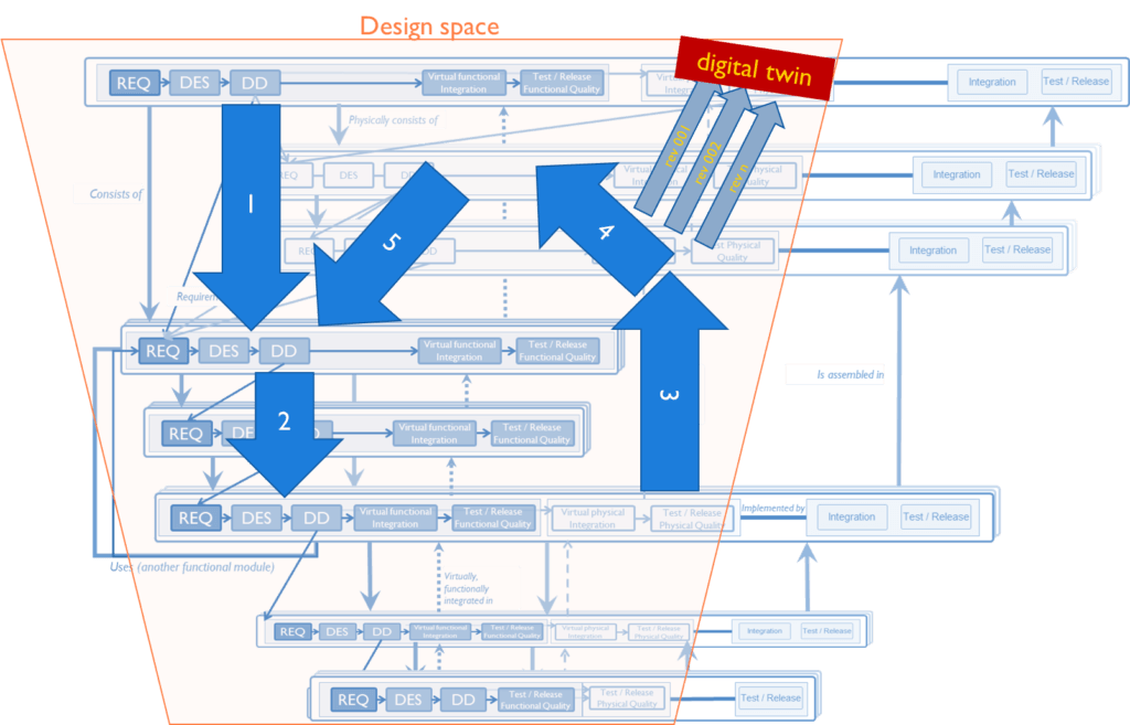
Design cycles with Digital Twin revisions as deliverables
One of the deliverables of the design activities can be a Digital Twin. As the development teams cycle through the different abstraction levels, from functional systems to building blocks and virtually integrate and test the coherence, completeness and quality of the designs, subsequent revisions of the System (System-of-Interest) are used to demonstrate compliance to both functional and physical system requirements (including the system’s behaviour).
Terms & acronyms used
- ⌊System-of-Interest⌋ [SoI]
- ⌊PLM⌋
- ⌊Digital Twin⌋
![]()